ACADEMY OF KNOWLEDGE

APPLICATION AND INSTALLATION OF MOBILE CABLES - OVERHEAD TRAVELLING CRANES, CRANES, FESTOONS, LIFTS, CRANE BELTS...

    RADIUS OF CURVATURE
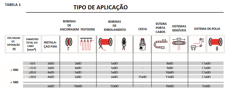

    These are the minimum bending radii for use in the different applications. You must strictly follow these recommendations and perform the correct bending calculation in order to obtain the best result and durability of the cable. Never increase the minimum bending radius stipulations because it causes elongation and internal torsions compromising the service life. The frequency of movement must also be taken into account, because if it is of low demand, the minimum bending radius may be tightened (slow or few movements).

    The table above gives the minimum recommended bending radii for different cable uses. Compliance with these recommendations and an accurate bending radius calculation is important as one of the most important reliability factors. Increasing the minimum bending radius has a more than proportional effect on the service life of a cable because it causes elongation and internal twisting due to increased mechanical stresses on the conductors.

    INSTALLATION - ANALYSIS OF THE CABLE GUIDE

    • Always use guides that allow the best bending radius with the smallest possible deflection.
    • Always keep the guides aligned to avoid twisting.

    A one-way system appears to be more economically advantageous. However, a considerable increase in rope life is obtained if a two-way guide is used: This does not occur if the winding system is fed at the end, remaining in contact with the rope regardless of the direction of travel of the machine.

    Use bidirectional or multiple guides whenever possible, continuing the arc beyond the angle of deflection. In this way the minimum radius of curvature is always maintained.


    Avoid any abrupt change of the bending radius, otherwise it may lead to a cable break.


    Always use voltage protection systems when laying the cable. The working voltages and protection devices must be defined in accordance with the parameters defined for each cable section.

    INSTALLATION - PULLEY ANALYSIS

    The weight of the pulleys increases the inertia, requiring more torque to compensate, increasing the tension on the cable, reducing its life. Also consider the contact of the outer rope cover with the pulley. Increase the contact area if using a hollow inner pulley.

    INCORRECT APPLICATION ON THE POLY: Effect induces torsion in the cable due to the rolling effect reducing its useful life.


    CORRECT APPLICATION ON THE POLY: Manner that minimizes the torsion applied to the cable.


    INSTALLATION - CHANGE OF DIRECTION

    Be aware of changes in direction by always leaving sufficient distance. It is recommended to use a distance of at least 20 times the outer diameter of the cable (especially in high-speed systems). This behaviour recovers the initial shape of the cable, before it is fatigued again.

    INSTALLATION - ANCHOR SYSTEM

    In order to maintain stable operation of the system, correct anchoring must be used. Different methods can be used, but there is a basic foundation: spread the tensile forces over a large area of the cable to avoid damage or failure at the anchor points.

    The most common mobile anchorage points are the "cable grips" type terminals. The load tension must be distributed along the whole cable length between 20 to 25 x its total diameter. In order to maintain operational movements leave a cable surplus before the entrance to the terminal box. When the centre point inner fitting is installed, the vertical distance between the entry mouth and the crane guide must not be less than 15 times the total cable diameter or 1m, use whichever is greater. At least 2 turns of cable must be made around the fixed relief drum to ensure sufficient contact area for proper stressing to occur.

    Dynamic strain on the cable can lead to premature failure, especially in high speed applications. To minimise this, various solutions can be used, but be aware of the speed reduction device. It is interesting to apply this system to your reel drive design, reducing the speed before reaching the centre point, then re-accelerating after passing the centre point and the direction of rotation of the reel has been reversed.


    1.  Cable holder
    2. Inlet
    3. Anti-stress rolling drum*
    4. Cable wound twice on the anti-stress winding drum
    5. Power cable
    6. Terminal box
    7. Clamp

    *(For Medium Voltage cables = 10 x Total Diameter; For Low Voltage cables = 5 x Total Diameter)

    INSTALLATION - REEL TYPES (DRUMS)

    A well-designed winding system, together with the correct choice of cables ensures reliability and a high durability. There are three main types of drums and they have advantages and disadvantages, let's see:

    1-) Mono spiral reel: this is the most common, with a simple guide route that gives the cable a longer life than other types. Also in these cable reels due to improved heat dissipation, the conductor size in power cables is generally smaller compared to other types of reels. The diameter and length of the cable is a major factor and must be taken into account when applying mono-spiral reels: good counterbalance between the inner and outer diameter of the reel will be critical in determining and controlling the tension of the cable.

    2-) Bobina de Torção Aleatória: O tipo mais simples de carretel existente. Ele opera sem guias e as camadas aleatórias podem criar dificuldades operacionais severas, tais como, derrapagem da bobina, força de tração abrupta, torções, abrasões e acúmulos anormais.  Por estes motivos, esta aplicação pode suportar apenas pequenos diâmetros de cabo e corridas curtas: 250 m de corrida máxima e um peso aproximado <4 kg / m.

    3-) Multi Spiral Reel: Used when the cable has a large diameter and long lengths. The main advantage of using this type of spool is its ability to transport large amounts of cable (even with large diameters) with constant winding tension and long distances. On the other hand, usually due to the location of the spool, it is also difficult to reduce the number of guides and changes of direction on this type of installation.

    COILS - HANDLING AND STORAGE

    Always use specialised personnel in order to obtain the best result. Test the entire system a few times before putting it into full operation in order to mitigate any faults that may occur.

    It is recommended to store and handle the cables on their respective reels in order to avoid defects caused by loose cables.

    Avoid rolling the drums on their flanges, use a fork lifter or crane to move the reel, if you cannot avoid rolling, do it against the winding direction in order to keep the cable tight to the reel and prevent twisting or abrupt tensions.
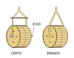
    Always keep the cables on their original reels. Store in a cool, dry and covered place. The ends of the cables should be closed, preferably with heat shrink, to avoid the entrance of humidity and dirt.

    Coil 11- In the case of lifting with a crane, the correct rope must be connected to an axle placed in the centre of the coil.* Attention:
    - Move as close to the ground as possible.
    .- Move slowly and when in the correct location, do not make an abrupt stop.
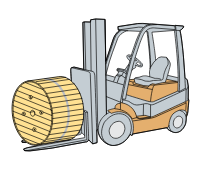


    Coil 22- In the case of a forklift truck, the drums must not be damaged by it.

    * Attention:
    - Place the coil in the centre of the fork.
    - The width of the fork should be greater than the coil.
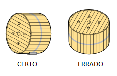


    Coil 33- Care when handling the cables:
    - Do not cover the coils.
    - Do not roll more than 20m.
    - Do not use sharp objects when moving.
    - Do not roll a damaged coil.
    - Do not roll on an uneven surface.
    - Do not store the coil near heaters or inflammable places.

    CABLE INSTALLATION

    When transferring the cables from the wooden reels to the system reels, try to transfer directly without passing through rollers or changing directions. The transfer should be done slowly and with minimum tension: this behaviour would avoid any twisting influence during cable installation.
    The following images show how to carry out the procedure:

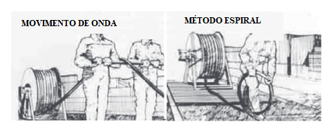
    REMOVAL OF THE TWIST:

    If, during the above procedure, the cable becomes twisted, it is strongly recommended to remove it. Normally two methods are provided for performing this action.
    1-) Wave motion:
    Insert a roller between 15 to 20 cm under the cable near the twist. At this point, two people should walk around holding the roller and pushing the "wave" to the end of the cable. You can perform this action until the detected twist is removed.
    2-) Spiral Method:
    This procedure can possibly be carried out by only one person. Leave enough slack in the fixed end to make a spiral, it should be a right or left side according to the direction of the twist detected. The spiral should be rolled to the free end of the cable to remove any twist. Perform the same procedure for each twist. Once the problem is solved put the cable back in to start the operation, if a small twist is still found, perform again the procedure and cut approximately 50 cm of cable in order to eliminate the twist. Test again and validate the test again.
    A properly installed cable, without any kinks, will remain stable in the system and will not kink throughout its life. To detect if twisting is occurring in the above tests, make some marks on the cable to detect possible twisting.
    Note: The marking may show a slight twist on long lengths of cable, this is normal and will not be related to any kind of twisting problem.

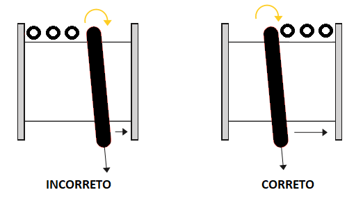
     CABLE INSTALLATION ON MULTI-SPIRAL REELS:
    INNOVCABLE's crane cables are manufactured with the conductors twisted to the right, consequently when winding on multi-spiral reels, the first turn should be with the cable meeting the right-hand reel flange. This will naturally maintain the tendency for the cable to form.

    INSTALLATION - VERTICAL APPLICATIONS - REELFLEX (K)NSHTÖU-J / (N)SHTÖU-J # REELFLEX PUR-HF # FESTFLEX (N) GRDGÖU

    Anchoring systems:

    The best result is obtained with a stress relieving coil. The open end construction makes installation and replacement easier by providing better stress relief and protection of the outer jacket than tightening the cable. Make at least 2 turns of cable around the drum. Table 1 (Bending Radius) shows the minimum bending radii for stress relief. If, on the other hand, anchoring is done with a tightening over the cover, a recommended length of cover over the cable is approximately 25 times the overall diameter of the cable. This will help spread the dynamic stresses over a sufficient surface area of the outer jacket to inhibit damage to the cable.


    REELFLEX (K)NSHTÖU-J / (N)SHTÖU-J and REELFLEX PUR-HF CABLE
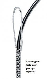
    When necessary, the lower part of these cables must be fixed with the correct tightening. The cover of the outer jacket is the same as that of the anchoring system (up to 25 x the rope diameter). The distance from the end of the anchoring device to the end of the machine stroke must be at least 40 x the rope diameter. If frequent dynamic stresses near the anchoring point are anticipated a spring can be used.

    FESTFLEX (N) GRDGÖU - BASKET APPLICATIONS
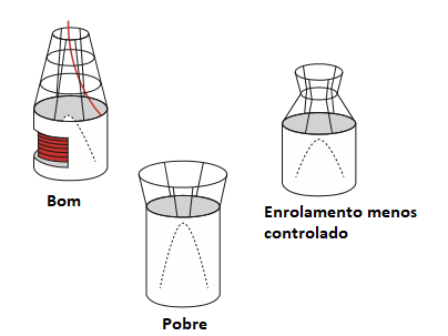
    The correct basket used is important for the correct operation of the system. High voltage applications involve long vertical lengths, high speed combined with rising and falling with movement and may have strong winds. Take care to ensure the diameter of the winding is not less than 1.5m. A guided centre cone placed in the basket is recommended to collect the cable correctly.
     The shape of the basket and the opening are also important operating factors: with high lifting and high speed a height of at least 2 m and a conical opening is recommended.
    Try to place the cable in the basket in an anti-clockwise direction from the outer layer of the original cable drum.

    ELECTRICAL PARAMETERS

    The electrical parameters are in accordance with DIN VDE 0298, part3 as per table 2.

    They are used in the flexible cables for voltage testing as required by DIN VDE 0250.

    CALCULATION OF CABLE CROSS SECTION

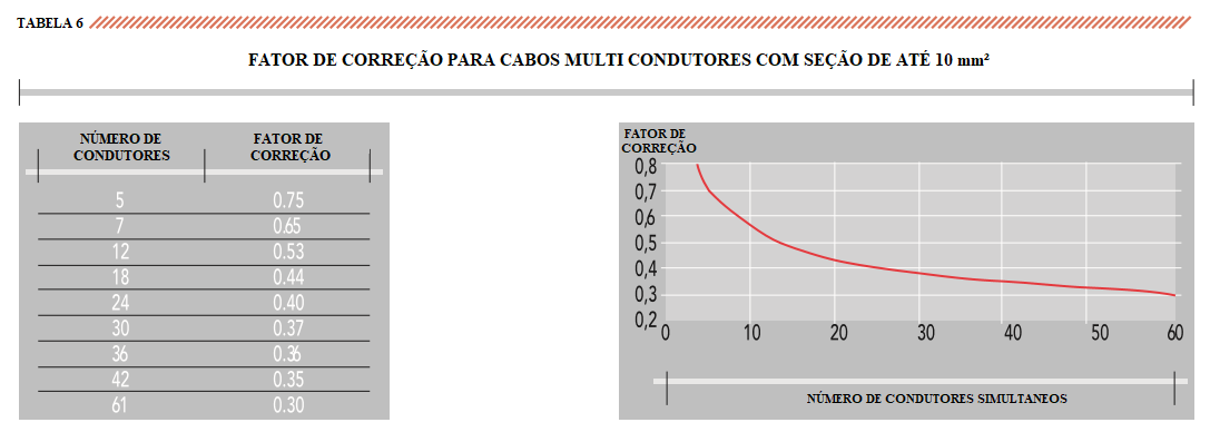
    For the transmission of a given current under operating conditions, the current capacities for the continuous operating conditions discussed in this case must be adopted and corrected. The adjustment may be required by means of correction factors for the relative conditions:
    - room temperature
    - number of layers and number of turns in the coil
    - number of drivers
    It should not be forgotten that non-continuous operation will mean better cable performance.
    With the real trend to increase cable running lengths it is interesting to check the voltage drop, not only for low voltages but for medium and high voltages as well.
    In some circumstances, it may be necessary to check the cable's resistance to short circuit currents, both from a thermal point of view and electro-dynamically induced forces.

    CURRENT CAPACITY FOR CONTINUOUS OPERATION

    The values below for direct current capacity and correction factors are in accordance with VDE 0298 part 4, 08-2003. The calculations were made for a conductor temperature of 80°C.

    The calculation was made according to VDE as a precaution because of the greater difficulties with heat dispersion for these types of cables. The values are for three-core cables, with or without earth conductor, without movement with the cable on the ground and with an ambient temperature of 30°C. For installations where it is known that cable life will be reduced as a result of high mechanical stress or wear on the outer jacket thermal ageing will be of lesser importance. A maximum operating temperature of 90°c may be considered in this case and the capacities given in Table 3 increased by approximately 7%.


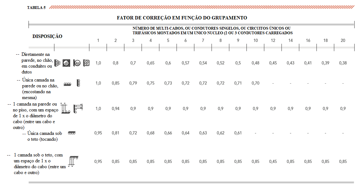
    The correction factors take into account the installation and operating conditions, such as temperature, grouping, intermittent use (number of movements during the day) and the number of conductors. Table 3 should be used for this.

    CURRENT CAPACITY FOR NON-CONTINUOUS OPERATION

    If operation is non-continuous or partially continuous it is advisable to check the values of the circulation and running times to see whether the cable cross-section can be reduced.

    Example of intermittent operation with lifting equipment with repeated cycles: a 10-minute operating period of full load is followed by a longer, no-load period. This 10 minutes taken as a percentage of the Total Cycle Duration (DT) provides a percentage load factor (CF).
    Load Factor FC % = (10 mi / DT) x 100
    In this case, the current load capacity calculated on the basis of table 3 can be increased with the factors given in table 7.

    SHORT-CIRCUIT CURRENT

     Short-circuit thermal limit
    In accordance with VDE 0250 c. 8/75, the permissible thermal limits for the short-circuit current in heavy mobile service cables must be calculated using the following reference values:
    Initial = 80 °c (full load cable)
    Final short circuit temperature = 200 °C
    The short-circuit currents (thermal limit) given in Table 8 have been calculated using these reference values and are valid for a time of 1 second.
    For other time periods, taking into account the protection characteristics, the table value must be divided by the square root of the effective time (in seconds). For different initial and final temperatures (i.e. with 90 °c and 250 °c admissible according to the standards), the short-circuit current (thermal limit) can be calculated using the following formula:

    ELECTRICAL PARAMETERS

     Three-phase voltage drop

    The voltage drop should be checked not only for low voltage, but also for medium voltage where the lengths are long. The value is calculated by multiplying the factors K (mV/Am) of the cable, by the length of the connection L (in km).
    Formula to calculate the voltage drop:
    V = I x L x K (Volt) where K =1.73 x (R cos + X sen )
    I = (A) current capacity
    L = (km) connection length
    R = (Ohm/km) a.c. conductor resistance at 80 °C (see table 10)
    X = (Ohm/km) cable reactance at 50 Hz (see table 10)
    The values for electrical resistance R (80 °C) and for reactance X (calculated for round 3-core + 3 earth cables, but valid also for flat cables with sufficient approximation) are also given in table 10.
    For conductor temperatures of 90 °C, resistance R must be multiplied by 1.03 while for a frequency of 60Hz, reactance X must be multiplied by 1.2 and the value for (mV/Am) recalculated.